Arduino Advent Calendar Day 03 - Light Dependent Resistor (aka Light Sensor)
Yesterday you blinked, faded and flickered an LED using a GPIO pin on your Arduino Board. GPIO stands for General Purpose Input Output. We did the OUTPUT side of GPIOs yesterday, today we're going to do the reverse using a light dependent resistor.
What is a Light Dependent Resistor?
We learned yesterday that resistors are a component that resists the flow of electrons through a circuit. A light dependent resistor is a component that changes its resistance depending on the amount of light.

How can we read resistance?
Our Arduino can measure voltage using the analogue input pins marked A0, A1, A2, A3, A4, and A5 but cannot measure resistance directly. To measure resistance, we must create a circuit called a "voltage divider circuit".
But first, what is this voltage thing?
Voltage is the difference in charge between two points, and it is distinct from current, which is the rate at which charge is flowing.
One way of thinking about the difference between voltage and current is to use the loose analogy of water in a hose, where the voltage is analogous to the pressure of the water in the hose, and current is the amount of water flowing through the hose. We can continue the analogy and imagine that resistance is like a kink in the line that impedes the flow of water.
Voltage divider circuits
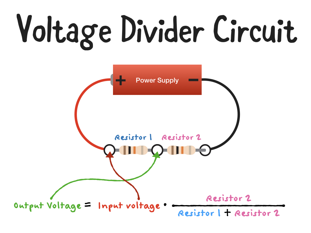
Voltage divider circuits rely on the fact that when we have two resistors in series as shown:

the output voltage is directly proportional to the input voltage and the ratio of two resistors.
In the above diagram we have two (four band) 10K resistors. If our power supply is providing us with 5V, the output voltage (between the two resistors) would be 2.5V.
If we were to switch out one of the resistors for the LDR, the output voltage would change depending on how much light there was in the room.
Our Resistors
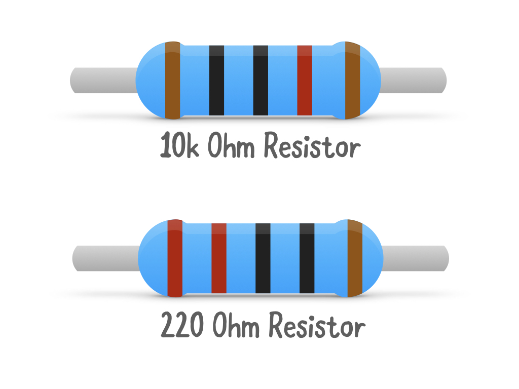
The resistors we have in our kits are 10k Ohm and 220 Ohm resistors.
For clarity, I've made the diagram below:

Enough talking about it, lets go and build up the circuit over at guides.littlebird.com.au .
|
Leave a comment