What is the electric imp? In essence, the Imp provides an easy, integrated way to connect almost any hardware device both to other devices and to internet services. It's more than just a WiFi card, or even a WiFi module with processing built in - it's an integrated platform that deals with the drudgery of connectivity, allowing you to concentrate on the application instead of the mechanics.
The Electric Imp is a WiFi enabled development platform powered by a Cortex-M3 processor core, the dimension is 32 x 24 x 2.1mm in a SD card form factor.
The Electric Imp API provides a set of classes and global objects with which imp code may access local hardware and remote cloud functionality. This API augments the
Squirrel Standard Library, which provides generic functionality. For more general information about the Squirrel language see Learning Squirrel.
An April breakout board will be strongly recommended to go with Electric Imp.
Features
802.11 b/g/n WiFi
•20MHz 11n channels, 1 x 1
•+16.75dBm max output power (802.11b)
•-97dBm typical sensitivity (1Mbps)
•Integrated antenna with 2.5dBi max gain
32-bit Cortex M3 processor
Robust embedded operating system with fail-safe firmware updates
•Virtual machine for vendor firmware
Embedded bi-color red/greenLED for status indication
Embedded phototransistor for our patent-pending BlinkUp optical configuration technology
6 user selectable I/Os
•GPIO, PWM, Analog input & output
•SPI (2 channels), UART (3 channels), I2C (2 channels)
Low power 6uA sleep mode
FCC, CE, IC C-Tick certified
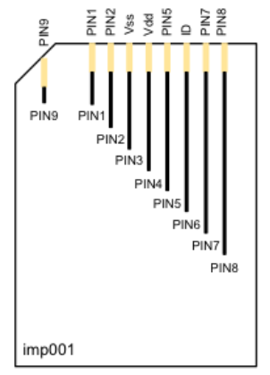
Pin assignments and description
|

|
Pin Number
|
Pin Name
|
Description
|
|
3
|
Vss
|
Ground
|
|
4
|
VDD
|
Power input
|
|
1,2,5,7,8&9
|
PIN1,2,5,7,8&9
|
I/O, please refer to Pin mux table
|
|
6
|
ID
|
Connects to the Atmel ATSHA ID chip
|
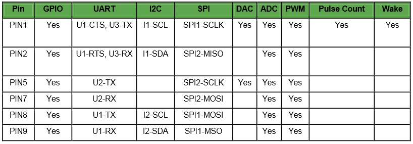
Pin mux
In addition to acting as a GPIO, each pin on the imp001 can be configured to one of several specialized functions. While pins may only have one function at a time, they may be reconfigured during run-time to change function as needed. For example, a pin may first be configured as a DAC and then reconfigured as an ADC. Additionally, not all the pins in a hardware function need to be assigned to that function. For example, pins 8 and 9 could be used as UART and pins 1 and 2 could be used as I2C.
All I/O pins are initially tri-stated.
The imp001 can be woken from low power sleep mode with a rising edge on PIN1. If this signal is pulsed, the minimum pulse width is 20ms.
Resources

